Column
How to Test a Hydraulic Pump: Step-by-Step Methods and Inspection Procedures
When operating construction equipment, it is not uncommon to encounter hydraulic system problems or breakdowns and be
unsure how to handle repairs or maintenance.
If the machine continues operating in that condition, a sudden shutdown can lead to major losses.
To prevent trouble before it occurs, regular diagnostics and accurate performance data are essential.
This article explains practical hydraulic pump testing methods and inspection procedures that help prevent failures on
the jobsite.
Use it as a guide to accurate measurement procedures and the proper steps for replacing parts with genuine components
so you can extend the service life of your construction equipment.
Why Hydraulic Pump Testing Is Necessary
To keep construction equipment operating reliably, hydraulic pump testing should be carried out regularly so
abnormalities can be detected early.
The hydraulic system is the core of the machine’s power transmission, and even a minor problem can directly reduce
overall performance.
To explain why testing is important, we will look at the following two points.
- Problems that can occur when measurements are neglected
- Key considerations for hydraulic systems in construction equipment
Regular testing can help prevent major failures.
Related Articles:Hydraulic Pump Maintenance: Preventive Tips, Failure Signs, and Service Life
Problems That Can Arise When Measurements Are Neglected
Failing to measure pressure and flow does not, in itself, cause a breakdown. However, without tracking changes in these readings, you may overlook reduced pump output or problems within the hydraulic circuit.
Consider testing in the following situations:
- When operating speeds decrease
- When unusual noises or heat buildup occur
- After hydraulic components have been repaired
- When a manufacturer-specified inspection is due
Take measurements under consistent oil temperature, engine speed, and load conditions, and compare the readings with the specified values and previous records.
Detecting problems early can help prevent damage from spreading.
Key Considerations for Hydraulic Systems in Construction Equipment
The rate of deterioration in a construction machine’s hydraulic system varies with the operating environment and the type of work performed.
Dust may enter through the oil filler opening, breather, or other points, while water can be introduced during filling or accumulate through condensation.
Keep in mind that different attachments require different pressures and flow rates.
Continuous operation under heavy loads can raise the oil temperature, affecting both measurement readings and the condition of the hydraulic oil.
During testing, record the oil temperature, engine speed, and load conditions, and compare the readings with reference values for the same conditions.
Do not apply a uniform inspection schedule or checklist to every machine. Determine what to inspect and when based on the machine’s operator’s manual, working environment, and operating conditions.
What to Check Before Testing a Hydraulic Pump
Careful preparation and inspection before measurement are essential if you want accurate hydraulic pump test results.
To carry out the work safely and accurately, make sure you do the following three things.
- Inspect the condition and level of the hydraulic fluid
- Bleed air from the piping
- Ensure safety and visually check for external damage and oil leaks
These checks will help improve the accuracy of the test.
Check Hydraulic Oil Condition and Level
Before testing the hydraulic pump, position the machine as specified in the operator’s manual and ensure that the hydraulic oil is at the specified temperature.
Then check the oil level using the oil level gauge.
Differences in oil temperature and machine position can affect the oil level and viscosity, making it difficult to compare test results accurately.
If the oil appears milky or contains metal particles, take a sample before changing it.
Record the sampling date and time, oil temperature, appearance, and odor to help identify the cause of contamination.
Then use the analysis results for contamination levels, water content, and wear metals to determine whether the hydraulic oil and filters need to be replaced and the circuit flushed.
Bleed Air from the Hydraulic Lines
Air may remain in the hydraulic circuit after hydraulic components or hoses have been replaced.
Consult the service manual for the specific machine model and use the designated air-bleeding port while keeping the pressure low.
Aeration, in which outside air enters through the piping, is different from cavitation, in which a drop in suction pressure causes bubbles to form in the hydraulic oil.
Depending on the cause, check the pipe connections, hydraulic oil level, and suction filter.
Loosening discharge-side fittings or valves while the machine is running can cause high-pressure oil to spray out.
If the procedure is unclear, do not attempt the work. Have a specialist carry it out.
Take Safety Precautions and Visually Inspect for Damage and Oil Leaks
Before installing measuring instruments, take the following safety precautions:
- Park on level ground.
- Lower the work equipment to the ground.
- Shut off the engine.
- Release any residual pressure in the hydraulic circuit.
- Wait for the hydraulic oil to cool.
- Wear protective equipment.
During the inspection, check for cracked or bulging hoses, loose fittings, and oil seepage.
High-pressure hydraulic oil can penetrate the skin, so never use your hands to locate a leak.
If damaged hoses or fittings are found, stop testing and consult a specialist.
After replacing the damaged components, confirm that it is safe to proceed before resuming measurements.
Specific Testing Procedures Using a Hydraulic Tester
On-site diagnosis is generally performed with a dedicated tester that can measure pressure and flow rate.
A portable tester allows you to narrow down the source of the problem without disassembling the machine.
To carry out the test, follow these three steps.
- Connect the tester to the piping and apply a load
- Measure and record pressure, flow rate, and hydraulic fluid temperature
- Compare the results with the reference values
Following the proper procedure makes it possible to assess the pump’s actual condition.
The Difference Between On-Site Measurements and Test Stand Testing
Hydraulic pumps can be tested on-site while still installed in the machine or removed for testing on a test stand.
On-site testing involves measuring pressure and flow under specific engine speed, hydraulic oil temperature, and load conditions.
Because this method assesses the hydraulic circuit as a whole, it makes it easier to reproduce the loss of force or slow operation experienced on-site.
However, the readings are affected not only by the pump’s condition but also by the condition of the valves, cylinders, and motors.
Test stand testing involves removing the pump and assessing its performance independently under controlled rotational speed, oil temperature, and pressure conditions.
This allows discharge flow, case drain flow, and the pump’s control response to load to be measured, making it easier to assess wear within the pump and verify its performance after repairs.
Start with on-site measurements to diagnose the hydraulic circuit as a whole, and consider test stand testing if an internal pump fault is suspected.
Connect the Test Equipment to the Hydraulic Lines and Apply a Load
Before connecting the test equipment, consult the hydraulic circuit diagram and the service manual for the specific machine model to identify the designated test ports.
When selecting the test equipment, check the following:
- Maximum working pressure
- Flow measurement range
- Compatibility with the hydraulic oil
- Flow direction
- Port connection specifications
Shut off the engine and release any residual hydraulic pressure before connecting the equipment, taking care to prevent contaminants from entering the system.
After starting the engine, bring the hydraulic oil to the specified temperature and set the engine to the specified speed for the machine model. Operate the loading valve according to the test equipment’s instruction manual.
Increase the pressure gradually while monitoring the gauges, and record the readings without exceeding the limits of the hydraulic circuit or the test equipment.
Measure and Record Pressure, Flow Rate, and Hydraulic Fluid Temperature
While the system is under load, read and record the values at the same time.
First, check whether the pressure reaches the specified value, then measure the flow rate at that pressure using the
flow meter.
At the same time, measure the hydraulic fluid temperature with a thermometer.
Because hydraulic pump performance changes depending on oil temperature, it is important to record all three values
together.
If you set multiple load levels and record the readings under each condition, you can get a clearer picture of how the pump’s performance changes under load.
Compare the Results with the Reference Values
Do not simply record the readings—compare them carefully with the standard values listed in the machine’s service
manual.
If the measured pressure does not reach the specified value, or if the flow rate drops sharply when the specified
pressure is applied, there may be an internal problem in the pump.
If the fluid temperature rises faster than normal, abnormal friction may be occurring inside the unit.
By objectively determining how much performance has deteriorated compared with the pump’s condition when new, you can
make an accurate diagnosis without relying on intuition alone.
This comparison is the foundation for building the right maintenance plan afterward.
Identifying the Cause of Failure from Hydraulic Pump Test Results
The data obtained from the tester provides reliable clues for identifying the cause of a failure.
Depending on which values are abnormal, it is often possible to narrow down the faulty component and the area that requires repair.
As a practical guide, focus on the following three situations.
- When pressure does not rise
- When flow rate is insufficient
- When both pressure and flow rate are abnormal
Identifying the cause accurately allows you to build a repair plan without unnecessary work.
Related Articles:Hydraulic System Troubleshooting: Common Problems, Causes, and Solutions
When Pressure Does Not Build Up
If the measured pressure does not reach the specified value, the relief valve is not necessarily at fault. To isolate the cause, check the following items in order:
- Pump rotational speed
- Hydraulic oil level and suction-side conditions
- Pump output performance
- Relief valve setting
- Internal leakage in valves or actuators
Take measurements under consistent oil temperature, engine speed, and load conditions, and compare the readings with the specifications for the machine model.
Incorrectly adjusting the relief valve or making errors during disassembly and cleaning can expose the hydraulic circuit to excessive pressure.
Have the work carried out by maintenance personnel who can consult the service documentation and verify the specified values.
Related Articles:Hydraulic Pump Not Building Pressure? Causes, Troubleshooting Steps, and Repair Costs
When Flow Rate Is Insufficient
If pressure is normal but the flow rate is extremely low, the pump is not drawing in enough oil.
If the suction filter is clogged with dirt or mud, suction resistance increases and the flow rate drops.
It is also not uncommon for air to be drawn in through the suction-side piping.
In some cases, the pistons and cylinder block inside the pump are severely worn, allowing the fluid that should be
discharged to leak back internally.
When this happens, the first step is to inspect the suction-line filter and hose connections and make sure there is a
smooth, unrestricted flow path for the oil.
When Both Pressure and Flow Are Abnormal
A simultaneous drop in pressure and flow does not necessarily mean the hydraulic pump has reached the end of its service life.
Possible causes include a low hydraulic oil level, a clogged suction filter, or air entering through the suction piping.
Also check for reduced engine speed, faults in drive components such as the coupling, and internal leakage through the relief valve or elsewhere in the circuit.
During diagnosis, measure pressure and flow at the pump outlet under consistent oil temperature, rotational speed, and load conditions.
Compare these results with readings taken on the actuator side to determine whether the loss of performance originates in the pump itself or in circuit components such as the valves.
When Case Drain Flow Increases
In pumps equipped with a case drain line, hydraulic oil from internal lubrication and leakage is returned to the tank.
Case drain flow is one indicator of internal pump wear.
As clearances between components such as the pistons and cylinder block increase, case drain flow may also rise.
When taking measurements, follow the service manual for the specific machine model and maintain the specified oil temperature, rotational speed, and load conditions.
Use a suitable flow meter or other appropriate instrument, and compare the readings with the manufacturer’s specified values and previous records. Do not block the case drain line, as this can raise pressure inside the pump casing and damage seals or other components.
Case drain flow also varies with hydraulic oil viscosity and temperature. Do not decide to replace the pump based on increased case drain flow alone.
Consider discharge pressure and flow measurements as well when determining whether the pump needs to be disassembled and inspected or replaced.
What to Do After Testing and How to Replace Parts Correctly with Genuine Components
Once an abnormality has been found, it is important to carry out the proper repair or parts replacement without
delay.
Using incompatible parts can lead to further failures, so the response must be handled carefully.
Use the following four points as a guide.
- How to decide between overhaul and replacement with genuine parts
- How to identify genuine parts quickly using a dedicated app
- How to reduce downtime by working with an authorized service center
- Guidelines for when regular maintenance and inspections should be performed
Choosing the right parts and maintaining the machine properly has a direct impact on performance.
How to Decide Between Overhaul and Replacement with Genuine Parts
If performance has declined, you need to decide whether to remove the pump for overhaul or replace it with a new
one.
If the problem is limited to minor scoring or deteriorated packings, performance may be restored through cleaning and
parts replacement.
However, if major components such as the pistons, cylinder block, or housing are heavily worn, partial repair will not
be enough, and replacing the unit is the more reliable option.
Whenever parts are replaced, use genuine components with proven quality and durability.
Cheap third-party, counterfeit, or imitation parts often do not fit precisely and can cause recurring problems, making
them unsuitable for the harsh conditions of a jobsite.
Related Articles:Hydraulic Pump Replacement Guide: Cost, Timing, Procedures, and Maintenance Tips
How to Identify Genuine Parts Quickly Using a Dedicated App
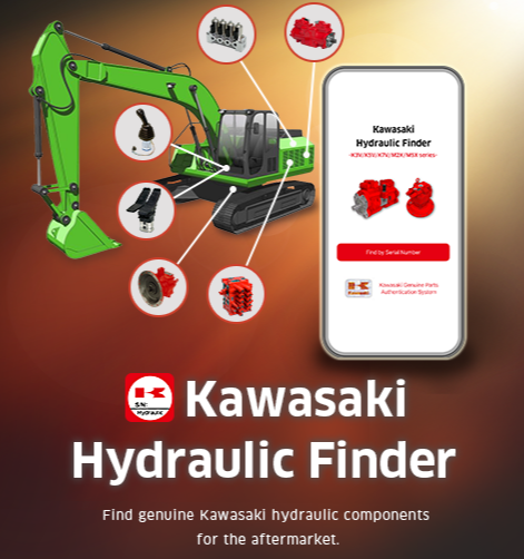
When you need to find the correct genuine parts on site, a dedicated app such as Kawasaki Hydraulic Finder can be
extremely helpful.
In the past, identifying parts often meant searching through thick catalogs or contacting the manufacturer directly.
With a dedicated app, you can simply enter the serial number from the nameplate on a smartphone or tablet and
instantly identify the correct genuine part.
This helps prevent delays caused by ordering mistakes or incompatible parts, allowing repairs to be completed more
quickly.
How to Reduce Downtime by Working with an Authorized Service Center
Because hydraulic pump overhaul requires advanced skills, it is wise to rely on an authorized service center if the
work is difficult to handle in-house.
Specialist technicians have manufacturer-recommended equipment and extensive experience, allowing them to detect and
repair even subtle abnormalities.
If you maintain a close relationship with a service center, arranging genuine parts and securing repair support will
go more smoothly when a failure does occur.
Having a cooperative relationship with skilled specialists is one of the best ways to prepare for unexpected trouble.
Guidelines for When Regular Maintenance and Inspections Should Be Performed
To keep the hydraulic system of construction equipment in good condition for as long as possible, it is important to
establish and follow a regular maintenance plan in addition to daily visual inspections.
As a general guideline, filters should be replaced and a test should be performed with a dedicated measuring
instrument at around every 1,000 operating hours.
It is also advisable to replace the hydraulic fluid completely at the same time.
When the machine has been used in harsh conditions involving heavy dust or muddy water, inspections should be moved
forward as needed.
Rather than waiting for parts to fail, establish a preventive maintenance approach on site by replacing components in
a planned way as performance begins to decline.
Summary: Extend the Service Life of Construction Equipment Through Accurate Hydraulic Pump Testing
To prevent performance loss and unexpected shutdowns in construction equipment, it is essential to use reliable
genuine parts when repairs or replacement are needed.
Low-quality non-genuine parts are also available on the market, and using them can lead to poorer fuel efficiency and
reduced operability.
Kawasaki Hydraulic Finder is a convenient way to confirm whether your hydraulic component is genuine and obtain
accurate replacement information.
By simply entering the serial number shown on the nameplate, you can identify genuine parts, confirm accurate
information, and contact an authorized dealer smoothly.
Be sure to make use of it.
Reviewed by

Ryoji Irie
Manager
After-Sales Promotion Office, Marketing & Sales Group, Precision Machinery & Robot Company, Kawasaki Heavy Industries, Ltd.
《Career History》
After joining Kawasaki Heavy Industries, I spent ten years developing the new K7V pump series as a design engineer, followed by five years at KPM (UK) as an application engineer supporting European OEMs and distributors. I am currently responsible for promoting the after-sales business globally.