Column
Variable Displacement Pump Guide: Structure, Working Principles, Pressure Adjustment, and Maintenance
Are you facing hydraulic system problems on a construction site or in a factory and unsure about the proper maintenance or repair procedures?
Understanding the pump’s structure and how to adjust pressure will help you respond quickly when trouble occurs.
This article explains how variable displacement hydraulic pumps work, how to identify the cause of pressure drops, and procedures such as air bleeding.
It also introduces a useful app that allows you to arrange genuine parts quickly from your smartphone, so use it as a reference if you are looking for better ways to manage hydraulic equipment.
Overview of Variable Displacement Hydraulic Pumps
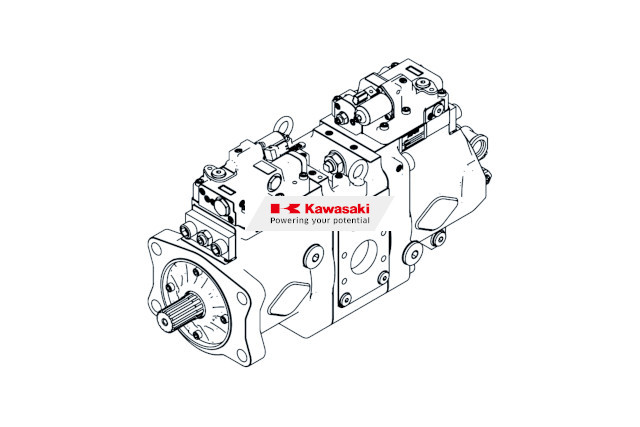
A variable displacement hydraulic pump is characterized by its ability to change discharge flow according to operating conditions.
To understand how this works, two concepts are essential: the difference between fixed displacement and variable displacement designs, and the meaning of displacement volume.
- Structural differences from fixed displacement pumps
- The basic meaning of displacement volume
Once you understand these two concepts, it becomes easier to identify the cause of failures and determine the right response.
Structural Differences from Fixed Displacement Pumps
Hydraulic pumps can be divided into two main types depending on whether the amount of fluid discharged per revolution can be changed.
A fixed displacement pump operates with a constant discharge volume per revolution.
Because its structure is simple and it uses fewer components, it is generally easier to keep costs down.
A variable displacement pump, on the other hand, is designed to change its discharge volume freely according to the operating condition of the equipment.
It can flexibly deliver only the flow required for the task and reduce discharge when flow is not needed.
Its strength lies in reducing wasted energy and transmitting power efficiently.
Related Articles:Hydraulic Pump Types Guide: Gear, Vane, and Piston Pumps for Construction Machinery
The Basic Meaning of Displacement Volume
Displacement volume refers to the volume of fluid discharged during one rotation of the pump shaft.
It is expressed in units such as cubic centimeters per revolution (cm³/rev) and serves as an indicator of pump performance.
By multiplying this displacement volume by the pump’s rotational speed, you can calculate the total discharge flow per minute.
In a fixed displacement pump, the displacement volume remains constant. In a variable displacement pump, however, this value can be changed by adjusting the internal angle or related mechanism.
To maintain the proper hydraulic pressure and flow for each type of work, it is important to understand the concept of displacement volume.
How Variable Displacement Piston Pumps Work
Piston pumps, which are commonly used in construction and industrial machinery, are known for their ability to handle higher pressure than other pump types.
To understand their operating principle, let’s look at the following two points.
- How the swash plate angle adjusts discharge flow
- Structural differences between hydraulic pumps and hydraulic motors
Understanding how these mechanisms work will help you troubleshoot problems on site.
Related Articles:Hydraulic Piston Pump Guide: Structure, Types, Operating Principles, and Failure Signs
How the Swash Plate Angle Adjusts Discharge Flow
Many variable displacement piston pumps adjust discharge flow by using the angle of an internal component called a swash plate.
A swash plate is an angled disc-shaped component that pushes and pulls the pistons.
When the swash plate angle is increased, the piston stroke becomes longer, increasing the discharge volume per revolution.
Conversely, when the angle is reduced, the piston stroke becomes shorter and the discharge volume decreases.
This angle is adjusted automatically by external control inputs or changes in hydraulic pressure.
It is an efficient design that produces the optimum power for the operating load while reducing unnecessary fuel consumption.
Structural Differences Between Hydraulic Pumps and Hydraulic Motors
Hydraulic pumps and hydraulic motors have similar structures, but the direction of energy conversion is completely different.
A hydraulic pump converts rotational force from an engine or other power source into hydraulic energy and pushes fluid into the system.
A hydraulic motor, on the other hand, receives pressurized fluid from the pump and converts that pressure into rotational force to move machinery.
You can think of the pump as the heart, sending fluid through the system, while the motor acts like the arms and legs that actually perform movement.
Knowing this difference in role is important when determining which component is causing trouble on site.
How to Adjust Hydraulic Pump Pressure
When operating equipment on site, there may be situations where hydraulic pressure needs to be changed according to the work being performed.
To carry out work safely, this section explains the following two points related to pressure adjustment.
- Understanding the function and role of the relief valve
- Setting pump discharge flow and pressure
Following these steps correctly helps protect the circuit while ensuring proper machine operation.
Understanding the Function and Role of the Relief Valve
The relief valve is a safety device that prevents pressure in the hydraulic circuit from rising too high.
When pressure in the circuit is about to exceed the preset upper limit, the relief valve opens automatically and diverts excess fluid back to the tank.
This helps prevent serious accidents such as ruptured piping or damaged equipment.
When you need to change the pressure, adjust the setting by turning the adjustment screw on the relief valve.
Tightening the screw increases the set pressure, while loosening it lowers the set pressure.
Because this adjustment is directly related to safety, always turn the screw gradually while monitoring the pressure gauge.
Setting Pump Discharge Flow and Pressure
On a variable displacement pump, discharge flow and maximum pressure can also be adjusted precisely on the pump body itself.
The side of the pump body is typically equipped with a discharge flow adjustment screw and a compensator for pressure adjustment.
When setting the maximum flow required for the work, operate the discharge flow adjustment screw to limit the maximum swash plate angle.
When setting pressure, turn the compensator screw so that the swash plate angle automatically moves toward zero once a certain pressure is reached.
By setting values that match the operating load, you can reduce energy loss while helping extend the service life of the equipment.
What to Do When a Hydraulic Pump Fails
When construction machinery or similar equipment is used for many years, unexpected problems can occur.
To minimize damage from trouble, this section explains the following three response procedures.
- Identify the cause of pressure loss
- Respond to abnormalities such as unusual noise and oil leaks
- Bleed air from inside the pump
By understanding common on-site symptoms and their causes, you can explain the situation more smoothly when contacting a repair service provider.
Identify the Cause of Pressure Loss
If hydraulic pressure does not build, the first step is to calmly determine where the problem is occurring.
One common cause is wear of internal pump components.
After many years of use, clearances between parts can widen, allowing fluid to escape and preventing the pump from generating sufficient pressure.
Pressure can also drop because of improper relief valve adjustment or leakage from pipe connections.
First, check the pressure gauge and confirm whether the pressure reaches the specified value.
Then inspect the pump body and surrounding valves in order to see whether there are any abnormalities.
Related Articles:Hydraulic Pump Not Building Pressure? Causes, Troubleshooting Steps, and Repair Costs
Respond to Abnormalities Such as Unusual Noise and Oil Leaks
If you hear an unfamiliar noise during operation or notice fluid leaking, you need to respond immediately.
Common causes of unusual noise include cavitation, a phenomenon in which local pressure drops cause the hydraulic fluid itself to vaporize and form bubbles, as well as damage to internal components.
If left unaddressed, these problems can lead to serious failure, so the machine must be stopped immediately and inspected.
Oil leaks are mainly caused by deterioration of pipe joints, packings, and similar sealing components.
The basic response is to identify the leaking location and replace the deteriorated parts with new ones.
Catching small abnormalities early is what prevents major trouble later.
Bleed Air from Inside the Pump
When a new pump has been installed or the fluid has been replaced, air must be removed from inside the pump.
Operating the machine with air still mixed in can cause unstable pressure and unusual noise.
First, loosen the air bleed plug located at a high point on the pump body.
Then pour clean hydraulic fluid into the pump to fill the inside with fluid.
After that, run the engine or drive source at low speed and wait until no more bubbles come out through the gap at the plug.
Once the bubbles have completely disappeared and only clean fluid flows out, tighten the plug to complete the process.
Maintenance Inspections and Parts Replacement for Continued Use
To keep a hydraulic pump operating in good condition, routine maintenance and replacement of consumable parts are essential.
For long-term operation, keep the following two points in mind.
- Carry out regular inspections at the appropriate frequency
- Use genuine parts to prevent trouble
To extend equipment life and avoid unexpected downtime, it is recommended that you establish a planned parts management and inspection schedule.
Carry Out Regular Inspections at the Appropriate Frequency
To prevent failures before they occur, it is essential to inspect the equipment according to a fixed schedule.
Before starting work, visually check whether the hydraulic fluid level is within the proper range and whether there are any leaks from the piping.
About once a month, also check the filter condition and the degree of hydraulic fluid deterioration.
If the hydraulic fluid has turned dark and cloudy or has an unusual odor, it may be a sign of fluid deterioration or abnormal internal heat generation and wear.
Every six months, have a qualified technician perform a detailed operational check to confirm that pressure and flow are normal.
The accumulation of these steady inspection practices supports stable machine operation.
Related Articles:Hydraulic Pump Maintenance: Preventive Tips, Failure Signs, and Service Life
Use Genuine Parts to Prevent Trouble
When replacing parts, using genuine parts specified by each manufacturer is the most reliable and safest approach.
Low-cost third-party parts, counterfeit parts, and imitation parts are available on the market, but they may not meet the required dimensional tolerances or material strength standards.
Using low-quality parts may damage nearby valves, cylinders, and other components as well.
As a result, repair costs may increase significantly, and the risk of the machine being out of service for an extended period also rises.
In many cases, the use of such parts may also void warranty coverage, so arrange genuine parts whose performance and safety are assured in order to protect the reliability of the entire machine.
Use an App to Arrange Genuine Parts Smoothly
When it becomes necessary to replace a part on site, have you ever been unsure which model number to order?
To help prevent ordering mistakes and the use of non-genuine parts, this section explains the following two points.
- Understand the risks of using non-genuine parts
- Identify the required parts from a smartphone
By introducing convenient digital tools, you can streamline parts selection and ordering tasks that used to take considerable time and effort.
Understand the Risks of Using Non-Genuine Parts
For equipment that operates in harsh environments, such as construction machinery, even a slight mismatch in a part can affect overall performance.
Even if non-genuine parts look the same, their pressure resistance and detailed dimensions often do not meet the manufacturer’s design standards.
Installing such parts increases the risk of early wear and fluid leaks.
Another disadvantage is that manufacturer support may no longer be available if an accident occurs.
To avoid unexpected downtime and unnecessary costs, it is safest to avoid parts of unknown origin.
Identify the Required Parts from a Smartphone
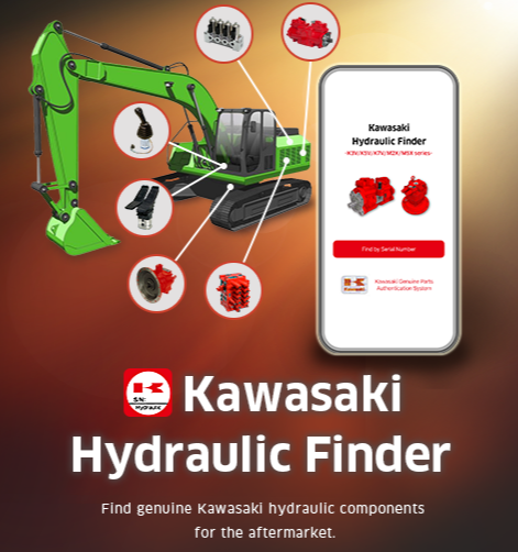
To arrange parts smoothly, we recommend using the app provided by Kawasaki Heavy Industries.
By installing the app on your smartphone and entering the serial number stamped on the pump, you can confirm whether the component is genuine.
If it is confirmed as genuine, the app can retrieve accurate model information.
If the serial number cannot be recognized, you can take a photo of the nameplate and send it to an authorized service center to request identification of the original model and confirmation of genuine status.
Using the identified part information, you can contact an authorized dealer and proceed directly with repair or ordering inquiries.
It is a convenient tool that allows accurate parts arrangements while you remain on site.
Summary: Understand How Variable Displacement Hydraulic Pumps Work and Carry Out Proper Maintenance Management
To keep hydraulic equipment in service for a long time, it is important to understand the pump structure and how pressure is adjusted, and to perform regular inspections without fail.
When a failure is suspected, accurately identify the cause and promptly replace deteriorated parts with genuine parts to reduce unexpected downtime and unnecessary costs.
When arranging parts, we recommend using an app such as “Kawasaki Hydraulic Finder,” which allows you to quickly confirm whether a part is genuine from the serial number on the nameplate.
Make use of tools like this as part of your day-to-day maintenance management.
Reviewed by

Ryoji Irie
Manager
After-Sales Promotion Office, Marketing & Sales Group, Precision Machinery & Robot Company, Kawasaki Heavy Industries, Ltd.
《Career History》
After joining Kawasaki Heavy Industries, I spent ten years developing the new K7V pump series as a design engineer, followed by five years at KPM (UK) as an application engineer supporting European OEMs and distributors. I am currently responsible for promoting the after-sales business globally.